Transformers Manufacturing Process
Electrical Controls & Switchgear Ltd (ECS) is driven by its commitment to quality. The complete in-house manufacturing process helps us to ensure optimum quality of the transformer. We have a complete testing facility to test and check all the major raw materials used in manufacturing the transformer. CRGO laminations are cut and annealed in the house to achieve minimum magnetic flux distortion. To ensure the best quality of the Coils of the transformer, winding wires and strips are also wound in house. The fabrication section ensures the robustness, quality, and fine finish of the tank and radiators of the transformer. The manufacturing processes of Distribution Transformers covers the following departments:-
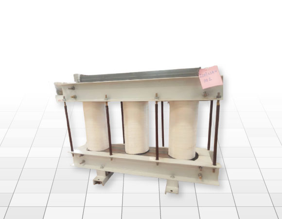
- Core Assembly
- Coil Winding
- Core-Coil Assembly
- Transformer Tank
- Painting & Finishing
- Tank-up


TRANSFORMER MANUFACTURING QUALITY CONTROL FLOW CHART
1. CORE ASSEMBLY
- The basic raw material is COLD ROLLED GRAIN ORIENTED (CRGO) Silicon Steel
- It is in the form of thin sheets & cut to size as per design.
- Generally, three different shapes of core laminations are used in one assembly.
- Notching is performed to increase the magnetic path.
- The laminations are put through the annealing process.
- These laminations are assembled in such a manner that there is no air gap between the joints of two consecutive sheets.
- The entire assembly is done on a frame commonly known as the core channel. These frames being used as clamping support of the core assembly
2. COIL WINDING (Coil Winding is of two types)
a) High Voltage (H.V) Coils:
- H.V. Coils are the components of finished transformers. They are made on automatic layer setting winding machines.
- A solid cylindrical former of predetermined diameter and length is being used as the limb over which is made.
- Generally, round insulated wire of either copper (Cu) or Aluminium (Al) is used as basic raw material.
- The coils are made in a number of layers.
- The starting and finishing leads of each coil are terminated on either side of the coil.
- These leads are properly sleeved and locked at a number of points.
b) Low Voltage Coils:
- L.V. Coils are also one of the components of the transformer. The procedure of making a low voltage coil is generally the same as described in (a) above.
- The shape of the basic raw material (Al or Cu) is rectangular.
- The Test: The “Turn Test” is carried out on the coils as per the required specifications.
3. CORE COIL ASSEMBLY
- The components produced in the coil winding and core assembly stages are then taken into the core-coil assembly stage.
- The core assembly is vertically placed with the footplate touching the ground and the top yoke of the core is removed. The limbs of the core are tightly wrapped with cotton tape and then varnished.
- A cylinder made out of insulating pressboard/ press pan paper is wrapped on all three limbs.
- A low Voltage Coil is placed on the insulated core limbs.
- Insulating blocks of specified thickness and number are placed both at the top and bottom of the L.V coil.
- Cylinder made out of corrugated paper or plain cylinder with oil ducts is provided over L.V coil.
- H.V. Coils are placed over the cylinder.
- The gap between each section of H.V. Coils including top & bottom clearances is maintained with the help of oil ducts, as per the design/drawings.
- The Top Yoke is refilled. The top core frame including core bolts and tie rods are fixed in position.
- Primary and secondary windings are connected as per the requirements. Phase barriers between H.V. phases are placed as per requirement.
- Connections to the tapping switch (if required) are made.
- Finally, the core coil assembly is placed in the oven for drying.
4. TRANSFORMER TANK
- ECS has a state-of-art in-house facility for manufacturing transformer tanks. All tanks are made of high-quality steel and can withstand vacuum as specified by the international standards and the customer.
- All welds are tested, ensuring 100% leakproof of seams and mechanical strength. Transformers with Corrugated Fin-Type radiators are also manufactured. The fins are manufactured of mild steel. The fin height and length are according to the customer’s specifications and fins can be plain or embossed. All transformer tanks are given a smooth finishing by using the seven-tank cleaning process.
5. PAINTING AND FINISHING PROCESS
Painting: The entire procedure of painting is done under two stages:
1. Cleaning of tanks
- The cleaning of the tank is done normally by chipping/grinding.
- The outside surface of the tank is cleaned using the seven-tank phosphate cleaning process.
2. Painting of tanks
- After cleaning the tanks, a coat of hot oil resistance paint is applied to the internal surface of the tank.
- The outside surface is painted with an epoxy powder coat or a coat of Red Oxide primer and subsequently with one coat of enamel paint as per the customer’s requirement.
Finishing:
- Fittings and accessories as per the customer’s specification and drawing are checked.
- Air Pressure test is subjected to avoid any leakage and seepage on all transformer.
- Transformers are filled with oil up to the minimum level marking, wherever necessary.
- Loose accessories like, earthing terminals, bimetallic connectors; dial-type thermometers are also checked for proper fittings.
6. TANK UP
The core-coil assembly and tank supplied by the fabrication department are then taken into the tank-up stage.
The procedure is:
- The core-coil assembly is taken out of the oven and the insulation resistance test is carried out.
- Only if the insulation resistance value is as per the specification, the assembly may be taken for tank-up.
- The tanks, supplied by the fabrication department are brought to the tank-up department duly painted.
- Fittings like drain valves, HV& LV Bushings, conservator, oil level indicator, and explosion vent are fitted in the tanks.
- The Core-coil assembly is then placed into the tank and properly locked up.
- Pure filtered transformer oil is filled in the tank to immerse the assembly only.
- Connections of primary and secondary to the terminal bushings are made. The operating handle for the ratio switch is fitted, wherever required.
7. TESTING
Once the transformer is tanked up and the tank sealed, then the testing of the transformer commences. The routine transformer tests carried out include
- Transformer winding resistance measurement.
- Transformer ratio test.
- Transformer vector group test.
- Measurement of impedance voltage/short circuit impedance (principal tap) and load loss (Short circuit test).
- Measurement of no-load loss and current (Open circuit test)
- Measurement of insulation resistance.
- Dielectric tests of a transformer.
- Tests on on-load tap-changer.
- Oil pressure test on the transformer to check against leakages past joints and gaskets.